Scan to BIM Best Practices
- Dan Edleson
- Sep 16, 2019
- 5 min read
Updated: Jan 29, 2020

Whenever you are working in Revit it is helpful to have a list of best practices. Some of the things that come up on typical projects are linking DWGs instead of importing them, using office standard families and organizing views into working and printed. A Scan to BIM model eventually ends up in the same place – a clean Revit model for documentation –but it takes a wildly different way to get there. Here’s some of the things I’ve found help to keep the process of Scan to BIM smooth and efficient and prevent major issues with modeling.
1. Limit the View Range
There is so much information in the scan data, if you don’t limit the range of your view you are going to spend a lot of time trying to figure out exactly what you are looking at. In the context of a section all you need to do is change the Far Clip Offset to 1’ or less to keep things tight. Since the section is shown in plans it’s easy to understand where you are cutting and be precise. Modifying the range in a floor plan takes a bit more work. To modify the Cut Plane in a floor plan you need to edit the View Range. A floor plan in the context of construction documents is typically cut somewhere around 4’ offset from the floor but that may not be where the most accurate data is in your scan. If you have 3’ tall windows with a 2’6” sill height and your view is set to cut off at 4’, suddenly the only thing you are looking at in a lot of places is the thickness of the window, without the wall. So there is a fine balance, especially in plan, about how you set the view range. In general I would say a 1’ or less clip is best for modeling off a point cloud, but you should always double check with a section box in 3D to be sure you aren’t obscuring critical elements.

2. Marking Unknown Thicknesses in Walls
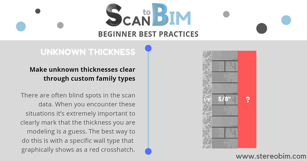
If the scan technician can’t get themselves or their equipment into a space it won’t be scanned. This often leaves blind spots in the scan data that will have to be verified another way. When you encounter these situations it’s important to clearly mark that the thickness you are modeling is a guess. The best way to do this is with a specific wall type and giving it a generic material that graphically shows as a red crosshatch when cut. What I usually do is create a wall type with two layers – finish and unknown. I will put the finish thickness as my best guess (for example if it is gypsum board I’ll make that layer 5/8”) then I will make the unknown layer 3” so the graphic display clearly shows up on all plans. If necessary you can do the same thing with ceilings and floors.

3. Verify with Photos
Whether they are hi-resolution photos from the scan or simply some taken on site, it’s important to verify with photos. What you are looking at is not always clear. Photos are a great way to confirm what you are looking at and help you better understand the scan data. One thing that is confusing when first modeling from scan data is the open doors in interior rooms. The doors are often open so the scan technician can freely walk through spaces, but what this does is leave a gap between the door and the wall in the scan, so that in plan it starts to look like the rooms have extra thick walls at each entry. Even looking at this type of situation in a 3D view can be confusing, but as soon as you see a photo of the room it is immediately clear what is going on. If you are working on a project where the interior is scanned but the exterior is not, it’s always a good idea to go on Google Maps and look at the exterior. Looking at the conditions from the outside can help better inform your modeling on the interior and is especially helpful for understanding any unclear conditions related to glazing or mullions.
4. Model Everything On Existing Phase
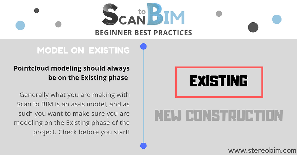
Hypothetically there may be a situation where this isn’t true, but generally what you are making with Scan to BIM is an as-is model, and as such you want to make sure you are modeling on the Existing phase of the project at all times. I have seen situations where people (myself included) have not realized they were modeling on the New Construction phase until they are done modeling. As long as you catch it before people begin documenting new work it’s a quick fix. First merge the phases. Now you have a single phase that the entire model is on. Rename this phase Existing, create a new phase and name it New Construction. Now all work is on Existing and you have your phases set up normally. The reason I suggest doing this rather than trying to select everything and change it manually is because certain elements such as curtain wall grids won’t want to switch phases.

5. Make Multiple Types, Limit Door and Window Families
Limiting the number of families on any project is good practice, but it becomes even more important on an as-built model where you may have doors with minuscule variation between them. As much as possible, and it certainly won’t always be possible, limit yourself to one parametric window family and one door family each. You can lay out everything in plan and then go into section and start refining things and adding as many types as you need.
6. Always Verify 3 Ways
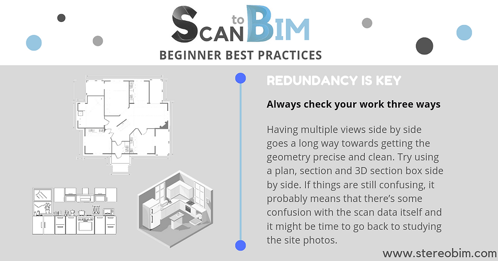
Redundancy is important for Scan to BIM projects. There’s a lot of cluttered information and it’s important to filter it down to see what is going on. In addition to all the ways we have already covered, having multiple views side by side goes a long way towards getting the geometry precise and clean. I generally suggest a plan, section and 3D section box. A trick with the 3D View Cube a lot of people don’t know; right-click on the cube, from the drop-down menu pick Orient to View and then pick any view in the entire project to orient to. Suddenly you have a section box set up to whatever you want to look at. If things are still confusing after looking over these three view types side by side, it probably means that there’s some confusion with the scan data itself and it might be time to go back to studying the site photos.

These are some of the best practices I have developed through my work producing Scan-to-BIM as-built models in Revit. It’s an evolving process, and I am constantly fine-tuning and adding to my process. Is there anything crucial you think I’ve missed? Anything related to Scan to BIM you’d like to see me cover in a future post? Let me know!
Comments